
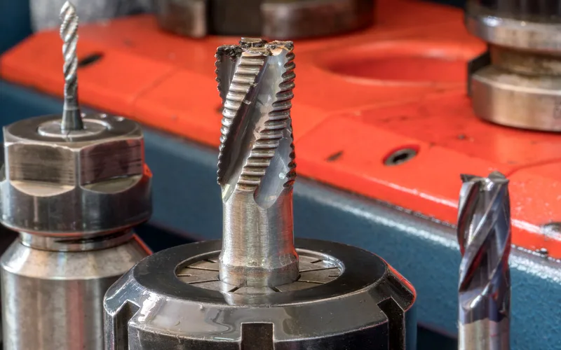
Most shops don't lose money on cutting tools because tools are expensive. They lose money because the wrong tool is quietly driving scrap, chatter, rework, and unplanned machine downtime — and the true cost never shows up on the tooling invoice. Cutting tools typically represent a small fraction of total machining cost, yet the tool you choose influences nearly everything else: cycle time, spindle hours, labor, and part quality.
Key Takeaways
- Tool failure is a symptom; the wrong tool selection is often the root cause.
- Wear pattern tells you why a tool failed — flank wear, cratering, chipping, and built-up edge each point to a different fix.
- Chatter is usually geometry, rigidity, or speed — not operator error.
- Matching substrate, coating, and geometry to the workpiece material is the single highest-leverage change most shops can make.
- Track cost per part, not cost per tool.
1. Your Tool Life Is Far Shorter Than It Should Be
If you're replacing inserts or end mills two or three times more often than the manufacturer's data suggests, the tool is telling you something. Premature failure rarely means you bought a "bad" tool — it usually means the tool was never right for the application.
Pull the tool and read the wear pattern under magnification before you throw it in the scrap bin. The failure mode is a diagnostic map:
What common wear patterns actually mean
| Wear pattern | Likely cause | Corrective action |
|---|---|---|
| Rapid flank wear | Cutting speed too high; abrasive workpiece; wrong grade | Reduce SFM, move to a harder/more wear-resistant grade or coating |
| Crater wear on rake face | Excessive heat and chemical diffusion at the chip interface | Improve coolant delivery, switch to a coated grade (AlTiN/TiAlN class) |
| Edge chipping | Interrupted cut, weak edge prep, unstable setup | Tougher substrate, honed/T-land edge, reduce feed on entry |
| Built-up edge (BUE) | Speed too low; gummy material (aluminum, low-carbon steel) | Increase SFM, polished flute geometry, higher rake angle |
| Thermal cracking | Inconsistent coolant / on-off thermal cycling | Apply coolant consistently or run dry with the correct grade |
| Catastrophic fracture | Overload, excessive DOC, chip re-cutting | Rigidity check, reduce engagement, improve chip evacuation |
2. Surface Finish Is Inconsistent — or Burrs Keep Coming Back
When parts start coming off the machine with visible tool marks, smeared surfaces, or burrs that require a secondary deburring operation, the tool geometry is usually the culprit. A finishing pass should not need a hand file behind it.
Watch for these geometry-driven finish problems:
- Too few flutes for the finish requirement. A 2-flute end mill clears chips well in aluminum but leaves a rougher finish in steel than a 4- or 5-flute tool at the same feed per tooth.
- Wrong corner radius or nose radius. Nose radius directly drives theoretical surface roughness at a given feed rate. Too small a radius forces you to slow down to hit spec.
- Insufficient rake angle for a gummy material. Stainless and soft aluminum need sharper, high-positive geometry to shear rather than push material.
- Wrong helix angle. High-helix tools shear more gradually and improve wall finish; low-helix tools are stronger but can leave witness marks.
- Running a roughing tool as a finisher. It works — until the tolerance tightens.
Burrs specifically are often a sign of a dull or under-sharp edge, or a tool exiting the material at the wrong angle. Before you add a deburring station, try the correct finishing geometry — it's almost always cheaper than the labor you're spending downstream.
3. You Hear Chatter, Squealing, or Vibration During the Cut
Chatter is the most audible sign of a tooling mismatch, and it's the one most often blamed on the machine. In reality, chatter is a resonance problem created by the interaction of tool overhang, flute count, cutting speed, and radial engagement. Refer to our popular blog to learn how to stop or reduce chatter.
How to diagnose chatter quickly
- Check length-to-diameter ratio. Deflection increases with the cube of tool overhang. If you're running a long tool because it was on the shelf, that's a tooling mismatch. Use the shortest tool that reaches the feature.
- Change the flute count or use a variable-helix tool. Unequal flute spacing disrupts the harmonic that sustains chatter — often the fastest single fix.
- Adjust radial depth of cut, not just speed. Light radial engagement with a higher feed (high-efficiency milling) is frequently more stable than a heavy conventional cut.
- Verify holder and setup rigidity. A premium end mill in a worn holder still chatters. Shrink-fit and hydraulic holders dramatically improve runout.
- Confirm runout. Anything above roughly 0.0004" TIR loads flutes unevenly and shortens tool life.
If a tool only performs well in a narrow, fragile window of speeds and feeds, it isn't the right tool for that job.
4. Cycle Times Are Creeping Up and Tool Changes Are Constant
This sign is economic rather than visual. If an operator has learned to "baby" a job — dialing the feed override down to 70% to get through the cut — the tool is dictating your throughput. Every tool change adds setup time, re-indexing, requalification, and lost spindle hours.
Quantify it with cost per part instead of cost per tool:
| Metric | What it reveals |
|---|---|
| Parts per edge / per tool | True consumable cost per finished part |
| Tool changes per shift | Hidden downtime and labor drain |
| Cycle time vs. quoted time | Whether tooling is eroding job margin |
| Scrap and rework rate | Quality cost attributable to tooling |
| Spindle utilization | Capacity you're losing to avoidable stoppages |
A tool that costs 40% more but doubles parts-per-edge and lets you run 20% faster is not the expensive option. Shops that make this switch often free up enough spindle capacity to take on additional work without buying another machine.
5. The Tool's Substrate, Coating, or Geometry Doesn't Match Your Material
This is the root cause behind most of the four signs above. Cutting tools are engineered for specific material groups, and a general-purpose tool used across titanium, hardened steel, and aluminum will underperform in all three.
Material-to-tooling quick reference
| Material | What the application needs | Common mismatch |
|---|---|---|
| Aluminum & non-ferrous | High positive rake, polished or ZrN/DLC flutes, 2–3 flutes | Steel-grade coated tools that cause BUE and chip packing |
| Carbon & alloy steel | TiAlN/AlTiN coating, balanced toughness grade, 4–5 flutes | Uncoated HSS run at carbide speeds |
| Stainless steel | Sharp edge prep, high-pressure coolant, heat-resistant coating | Low SFM causing work hardening and rapid notch wear |
| Titanium & superalloys | Low SFM, heavy coolant, high-helix, wear-resistant grade | Standard steel parameters, leading to thermal failure |
| Hardened steel (45+ HRC) | Rigid setup, negative geometry, CBN or hard-milling carbide | Standard carbide, resulting in instant edge breakdown |
| Cast iron | Abrasion-resistant grade, often dry machining | Coolant-dependent grades and coatings that crack thermally |
| Composites & plastics | Compression or diamond-coated geometry | Metal-cutting geometry that delaminates or melts material |
Coating is not a cosmetic detail. A TiAlN coating forms a protective aluminum-oxide layer at high cutting temperatures — excellent in steel, counterproductive in aluminum where it promotes adhesion. Substrate grade, edge prep, and coating have to be selected together, as a system.
How Do You Fix a Cutting Tool Mismatch?
Work through these steps in order before changing tooling brands:
- Define the material precisely — including alloy, temper, and hardness, not just "steel."
- Read the wear pattern on the failed tool and map it to a cause using the table above.
- Verify speeds and feeds against the manufacturer's data for that exact grade and material group — not a generic chart.
- Check the setup: holder condition, runout, overhang, workholding rigidity, and coolant delivery.
- Change one variable at a time and document the result so you build repeatable process knowledge.
- Bring in application support when the fix isn't obvious. A tooling specialist who can review the part, material, and machine will often find time savings a catalog can't.
Frequently Asked Questions
How do I know if my cutting tool is wrong or just worn out?
A worn tool degrades gradually and predictably at the expected number of parts. A wrong tool fails early, fails inconsistently, or produces defects — chatter, burrs, poor finish — from the very first part. If a fresh tool still cuts poorly, the problem is selection or setup, not wear.
What is the most common cutting tool selection mistake?
Using one general-purpose tool across multiple material groups. A tool optimized for carbon steel will build up edge in aluminum and fail thermally in titanium. Matching grade, coating, and geometry to the specific material is the highest-impact correction most shops can make.
Does a more expensive cutting tool actually save money?
Often, yes — because tooling is a small fraction of total machining cost. A premium tool that doubles tool life, permits higher feed rates, and reduces scrap can lower total cost per part even at a significantly higher purchase price. Evaluate cost per part, not cost per tool.
What causes chatter when milling?
Chatter is a self-sustaining vibration caused by resonance between the tool, holder, machine, and workpiece. The most common contributors are excessive tool overhang, insufficient setup rigidity, uniform flute spacing, excessive radial engagement, and cutting speeds that align with the system's natural frequency.
How often should cutting tools be replaced?
Replace based on measured wear or part quality, not a fixed calendar. Establish a baseline of parts-per-edge for each job, monitor flank wear against a defined limit (typically 0.012"–0.015" for finishing work), and replace before wear accelerates into catastrophic failure that can damage the part or spindle.
Can the wrong cutting tool damage my machine?
Yes. An overloaded or improperly selected tool increases cutting forces, which accelerates spindle bearing wear, degrades holder accuracy, and in a catastrophic fracture can damage the workpiece, fixture, or spindle taper. Tooling mismatches are a maintenance issue as well as a quality issue.
Not Sure Which Cutting Tool Is Right for Your Application?
A&M Industrial's metalworking specialists help shops diagnose tool failures, optimize speeds and feeds, and select the right tooling from leading cutting tool manufacturers — including Emuge, Garr, Guhring, Harvey Tool, Iscar, Kennametal, Korloy, Nachi, OSG, and Tungaloy-NTK. Bring us the part, the material, and the problem, and we'll help you cut cycle time and scrap.
Request Metalworking Support